Quick Start
This guide walks you through adding pinch support to the Arduino IDE and uploading your first sketch.
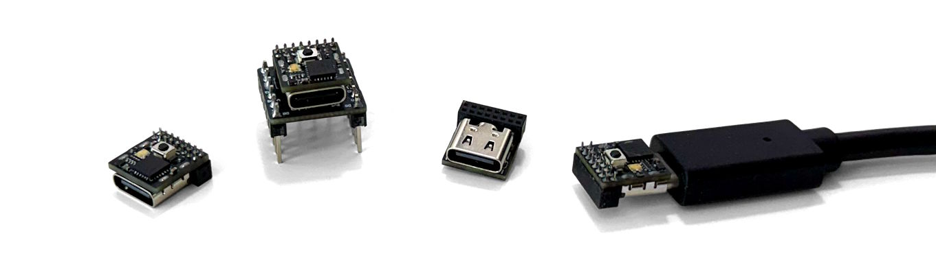
What you need
- A pinch Dev Board
- A USB-C data cable
- Arduino IDE (tested on v2.3.x)
Install the pinch board package
-
Open the Arduino IDE.
-
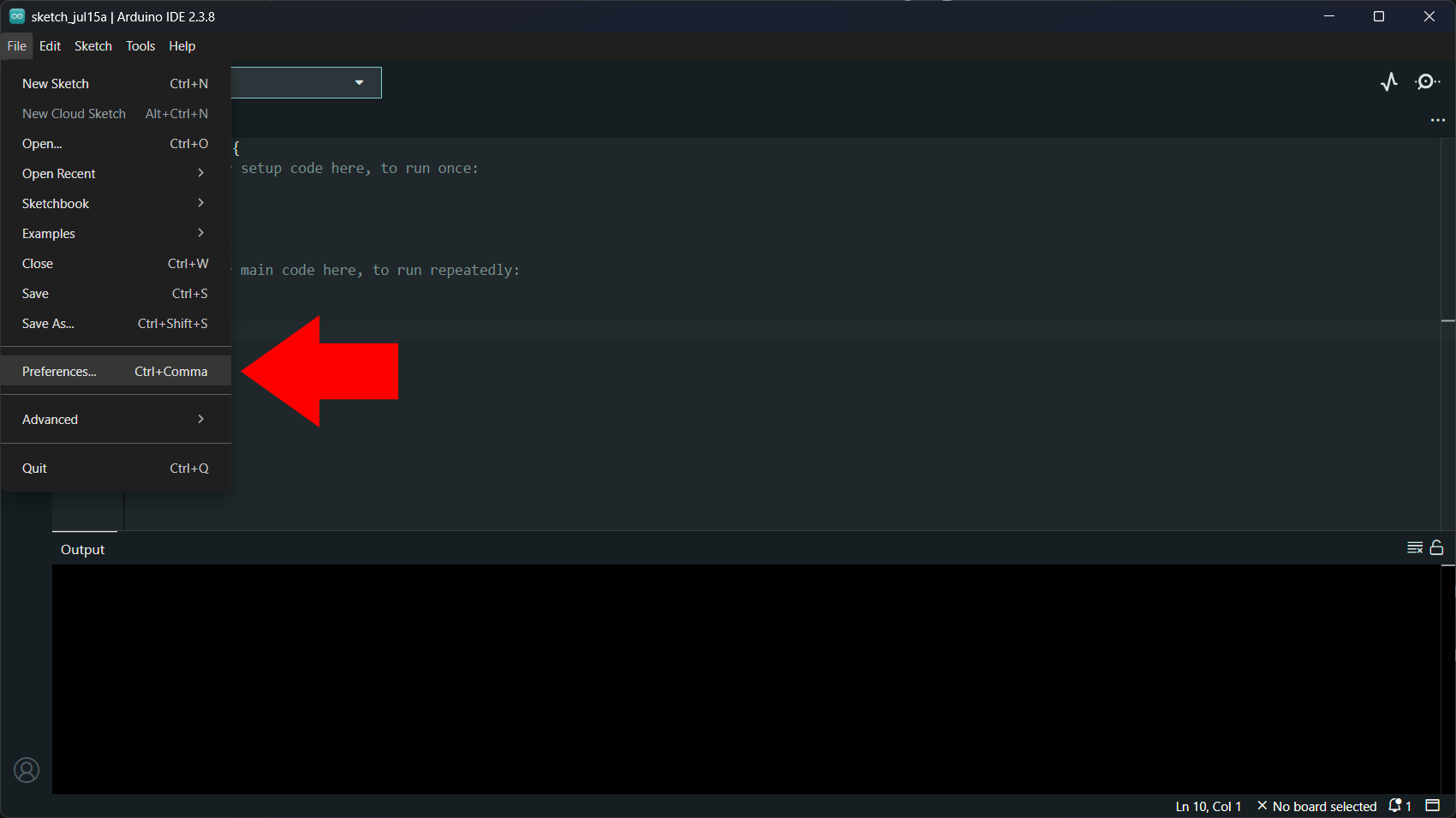
Go to File → Preferences.
-
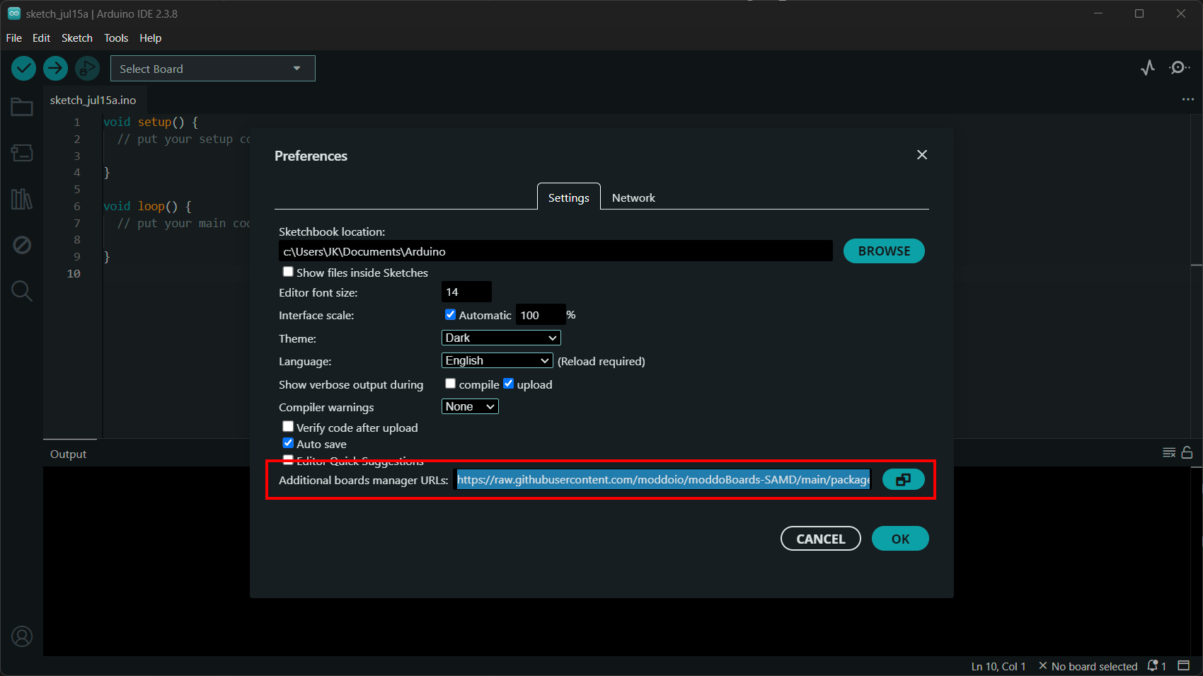
Find Additional Boards Manager URLs and add the following URL:
https://raw.githubusercontent.com/moddoio/moddoBoards-SAMD/main/package_moddo_index.jsonIf other URLs are already listed, click the button beside the field and add the URL on a new line.
-
Click OK to save your preferences.
-
Go to Tools → Board → Boards Manager.
-
Search for moddo SAMD Boards and click Install.
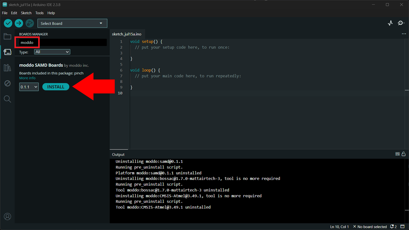
The Arduino IDE downloads the required compiler, upload tool, and supporting files automatically.
Select and connect pinch
-
Connect the pinch Dev Board to your computer with a USB-C data cable.
-
Open the board selector and choose the port that appeared when you connected pinch.
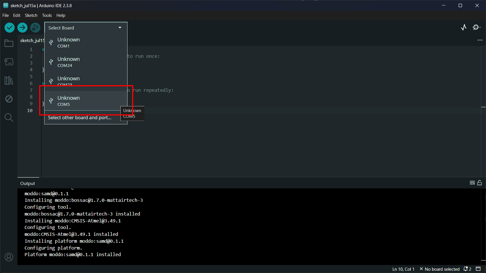 note
noteThe screenshots show
COM5, but the COM port number will be different on your computer. -
If Arduino IDE does not identify the board automatically, click Select other board and port, search for pinch, select the board and its port, and click OK.
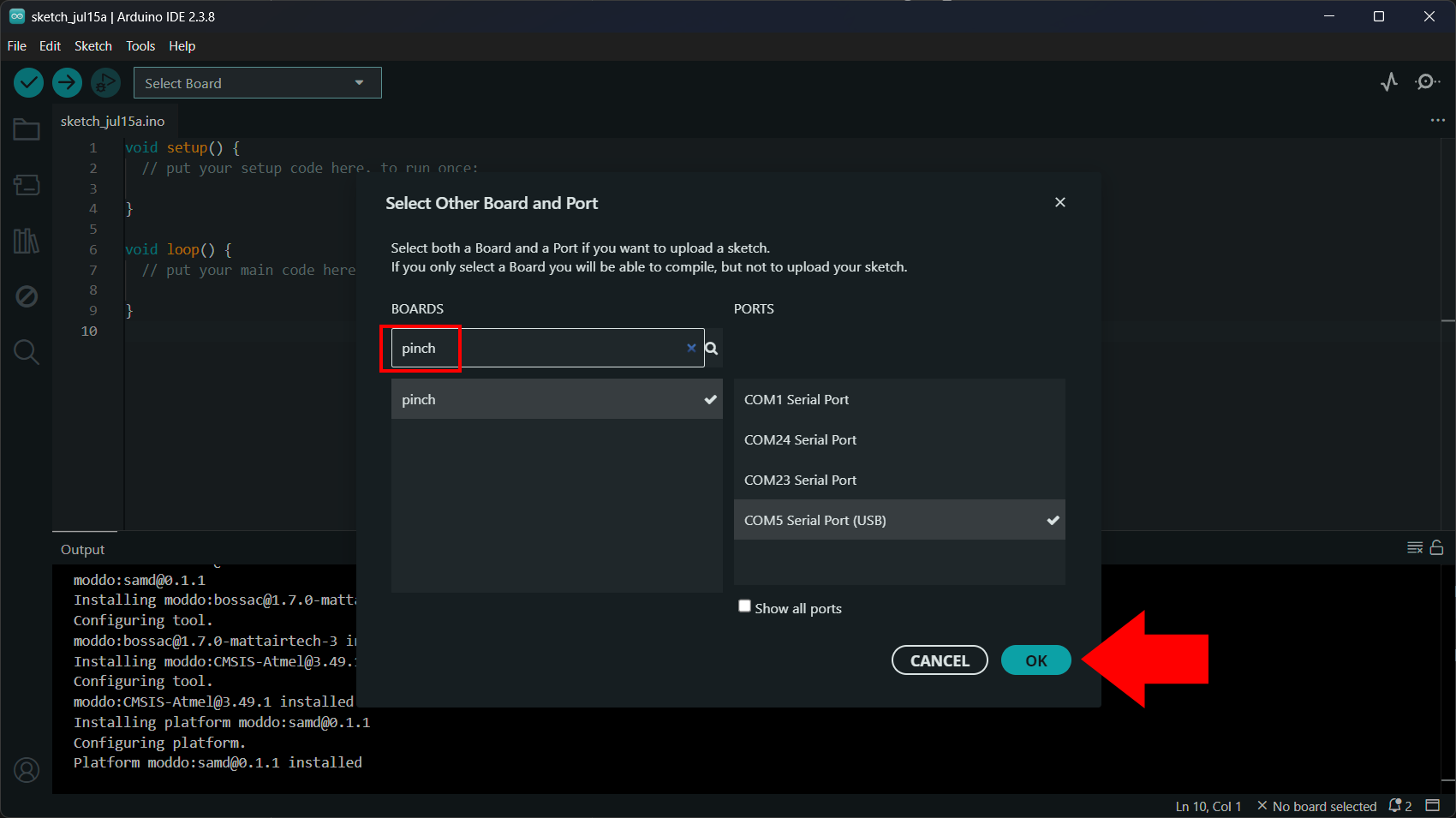
Most sketches can use the default options shown in the Tools menu.
Upload your first sketch
The built-in RGB LEDs are active-low: LOW turns a color on and HIGH turns
it off. Copy this sketch into the Arduino IDE to test each color:
void setup() {
  pinMode(PIN_LED_RED, OUTPUT);
  pinMode(PIN_LED_GREEN, OUTPUT);
  pinMode(PIN_LED_BLUE, OUTPUT);

  // Start with all colors off.
  digitalWrite(PIN_LED_RED, HIGH);
  digitalWrite(PIN_LED_GREEN, HIGH);
  digitalWrite(PIN_LED_BLUE, HIGH);
}

void loop() {
  digitalWrite(PIN_LED_RED, LOW);
  delay(500);
  digitalWrite(PIN_LED_RED, HIGH);

  digitalWrite(PIN_LED_GREEN, LOW);
  delay(500);
  digitalWrite(PIN_LED_GREEN, HIGH);

  digitalWrite(PIN_LED_BLUE, LOW);
  delay(500);
  digitalWrite(PIN_LED_BLUE, HIGH);
}
Click Upload. When the upload finishes, the RGB LED should cycle through red, green, and blue.
If the upload fails
Double-tap the RST button to put pinch into bootloader mode, select its port again under Tools → Port, and retry the upload. Manual bootloader mode is useful when a previous sketch has disabled USB or is preventing the board from responding.
For full-color LED control, open File → Examples → pinch → RGB_LED.