Introduction
The moddoMOUSE is built with expansion in mind. At its core is the Main Board which houses the optical sensor, wireless micrcocontroller, and other peripherals. On either side sit two expansion slots, the Front Board and the Back Board, where each are connected to the Main Board via a dedicated connectors. For this section, we are mainly concerned with pins that exposes power, I2C/TWI (Inter-Integrated Circuit/Two-Wire Interface), and interrupt pins.
Pinout Overview
The Main Board exposes two expansion connectors on each side: one on the left edge and one on the right edge. Together they form the Front Board connector (J30 + J31) and the Back Board connector (J40 + J41) as shown in the below figure.
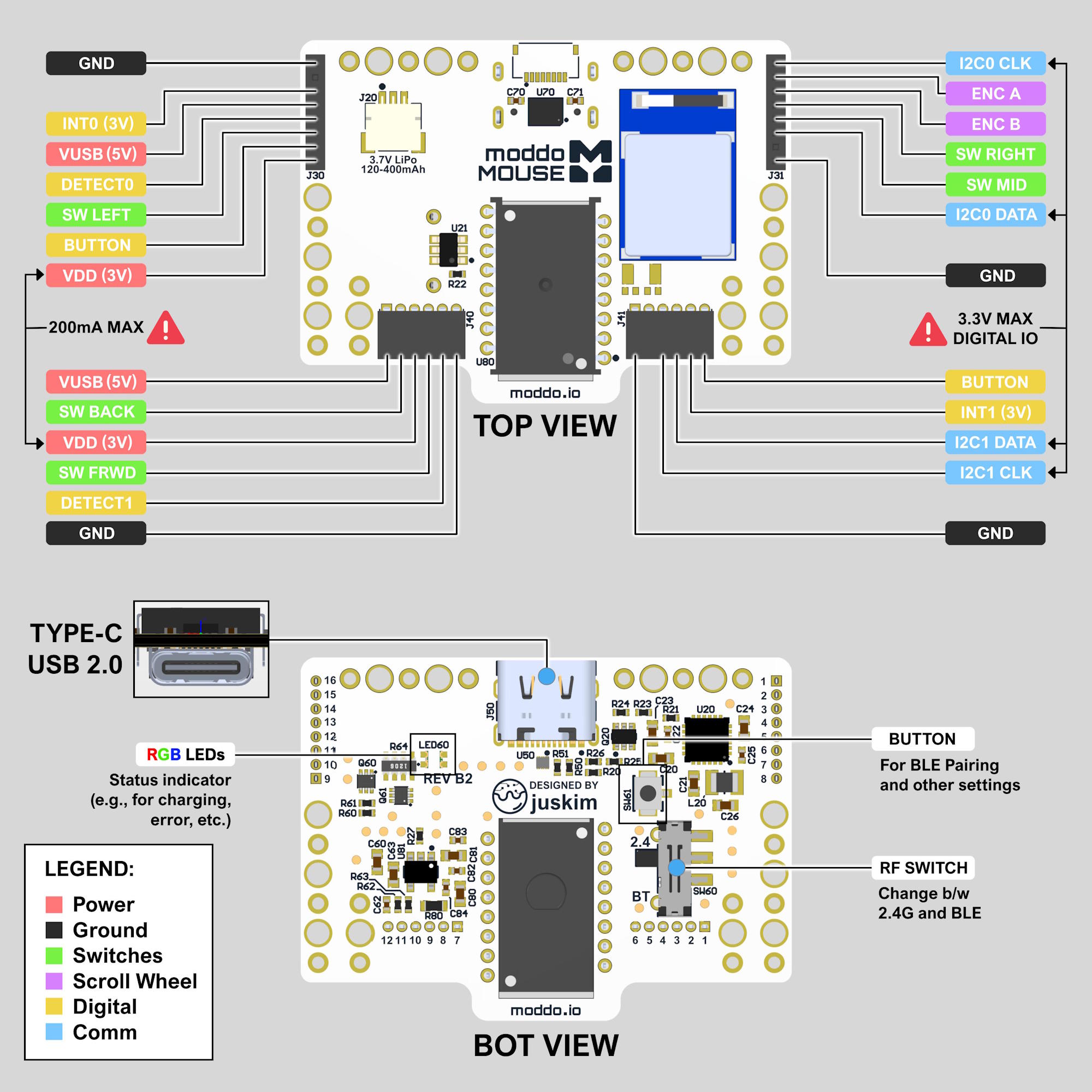
The Front and Back boards each have their own dedicated I2C bus: I2C0 for the Front Board and I2C1 for the Back Board. This means both expansion boards can be active at the same time without interfering with each other.
Front Board (J30 / J31): I2C0
| Pin | Function |
|---|---|
| VDD (3V) | 3V power supply from the Main Board (200mA max) |
| GND | Ground |
| I2C0 SDA | I2C0 data line (3.3V max) |
| I2C0 SCL | I2C0 clock line (3.3V max) |
| INT0 (3V) | Interrupt output from the Main Board |
Back Board (J40 / J41): I2C1
| Pin | Function |
|---|---|
| VDD (3V) | 3V power supply from the Main Board (200mA max) |
| GND | Ground |
| I2C1 SDA | I2C1 data line (3.3V max) |
| I2C1 SCL | I2C1 clock line (3.3V max) |
| INT1 (3V) | Interrupt output from the Main Board |
⚠️ All I2C and interrupt lines are 3.3V logic. Do not drive them above 3.3V or you risk damaging the Main Board. VDD is rated at 200mA max (Front and Back combined). Keep your expansion boards' current draw within this limit.